Design note: Remote weather station using Thread
5 November, 2015
A complete remote weather station based on a single Kinetis microcontroller with wireless connectivity

A complete remote weather station based on a single Kinetis microcontroller with wireless connectivity
Kevin Kemp, Freescale
Over the past year, a series of IoT themed senior design projects by students at Texas State University were created based on Kinetis microcontrollers and Thread wireless networking technology.
One of the projects was a remote weather station that measures temperature, barometric pressure, wind speed, wind direction and rainfall, and transmits the data over a Thread network. This is a great IoT application example that uses multiple sensors – each with very different functional, timing and signal characteristics – and can be easily implemented using a single Kinetis microcontroller that has wireless connectivity.
Key components of the weather station
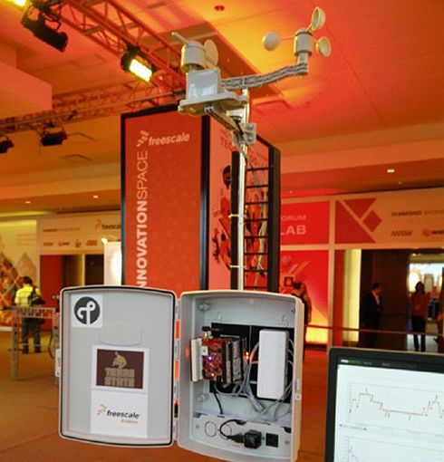
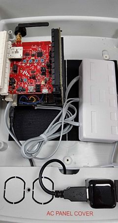
The weather station is designed around a TWR-KW24D512 Kinetis Tower System module, which provides the necessary microcontroller functionality for the sensors and wireless connectivity for the Thread networking protocol. The anemometer (wind speed), weather vane (wind direction) and rain gauge sensor functions are implemented using a SparkFun SEN 08942 Weather Meter kit. A TWRPI-MPL115A2 barometer attached to the TWR-KW24 board is used to measure atmospheric pressure.
A TMP36 analog temperature sensor is used to measure ambient temperature. A TWR-PROTO board together with a TWR-ELEV system provides space for additional circuitry and robust connections to the external sensors.
The electronic components (excluding most of the sensors) are contained in a weatherproof enclosure mounted to the base of the weather station mast. The entire station is powered from a USB adapter plugged into a 110V AC outlet. The sensors are all connected via modular RJ11 jacks.
TWR-KW24 Configuration
Together with the integrated low power 2.4 GHz IEEE 802.15.4 2011 radio frequency transceiver, the MKW24D512 device includes:
- 50 MHz ARM CortexM4 Core (1.25 MIPS/MHz)
- 512 KB of flash and 64 KB of RAM Power management controller with 10 different power modes
- Security features including, secure flash, tamper detect, cryptography acceleration unit and 128bit random number generator
- 16bit SAR ADC with one differential and up to 11 single-ended external analog inputs
- Various timer modules including FlexTimer, Periodic Interrupt Timer, Programmable Delay Block and Independent Real –Time clock
- USB, SPI, UART, and I2C interfaces
- Up to 28 GPIO channels
The sensors used for the weather station project use two ADC channels for the wind vane and temperature sensor, two GPIO channels for the wind speed and rain gauge and an I2C channel via the TWRPI connector for the barometric pressure sensor.
Sensor algorithms
The sensors each have very different functional, timing and signal characteristics, so one of the challenges of this project was developing appropriate interfaces and algorithms for each of the sensors and getting them to all work together. The resulting implementation is based on a main sampling loop triggered by a 10ms periodic interrupt timer, with a callback function that executes the measurement algorithm for each sensor.
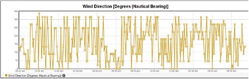
Wind vane
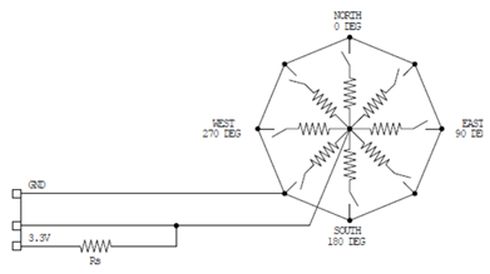
The wind vane sensor is a voltage divider consisting of a resistor array connected with eight magnetic reed switches. A magnet on the wind vane closes either one or two adjacent switches depending on the wind direction. This produces one of 16 different voltage levels corresponding to 16 discrete compass directions. The voltage is measured on one of the ADC channels and a lookup table is used to translate each voltage range to a corresponding wind direction. However, because the voltage levels do not change monotonically with wind direction we implemented a debounce algorithm to ensure that voltage transitions are not interpreted as an incorrect direction.
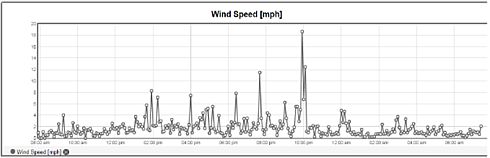
Anemometer
The wind speed measurement uses a cup-type anemometer with a magnetic reed switch that generates a pulse with each half rotation. One pulse per second corresponds to a wind speed of 1.492 miles per hour. In order to provide sufficient accuracy over a wide range of wind speeds, the measurement algorithm measures the interval between pulses. A GPIO input channel is configured to trigger an interrupt on the rising edge of each pulse. The interrupt sets a flag that is checked every 10ms by the main measurement loop, and a software counter records the number of 10ms intervals since the previous pulse. If the flag has been set, the wind speed is calculated from the counter value and the counter is reset; if not the counter is simply incremented. This solution provides an error of <10% for wind speeds up to 15 miles per hour and a maximum measurement of 149.2 miles per hour. A 30 second timeout defaults the measured wind speed to zero for wind speeds less than 0.05 mile per hour.
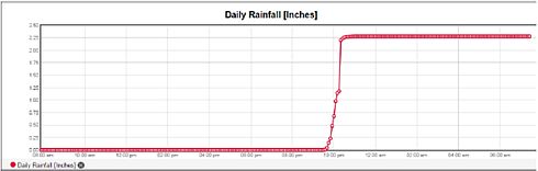
Rain gauge
The rain gauge measures rainfall using a self-emptying bucket with a magnetic reed switch that generates a pulse each time the bucket tips. Each tip of the bucket indicates 0.011 inches of rainfall. Similar to the anemometer, a GPIO input channel is configured to trigger an interrupt on the rising edge of each pulse. A software counter records the number of accumulated pulses and thus the total rainfall. A debounce function eliminates spurious counts from the reed switch.
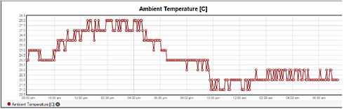
Temperature
The TMP36 analog temperature sensor was selected to measure ambient air temperature. The sensor is protected from the elements and direct sunlight in a simple housing made from PVC plumbing parts. The temperature sensor is powered by 3.3V DC from the TWR-KW24D512 board and produces an analog output voltage that is linear with temperature. The output voltage is measured on one of the KW24 ADC channels and translated to temperature using specified calibration values. During initial testing we noticed some crosstalk between the temperature sensor and wind direction sensors, which are both measured using multiplexed channels on the same ADC. This problem was solved by alternating these measurements between successive 10ms sampling intervals to allow sufficient settling time on the ADC input. In addition, we filtered the measured temperature using a 50 sample moving average to reduce noise.
Barometer
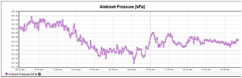
The MPL115A2 absolute digital pressure sensor uses a MEMs pressure sensor and an onboard processor to convert the atmospheric pressure measurement to a 16 bit digital value that is communicated over an I2C interface. The TWRPI-MPL115A2 module is attached to the TWRPI connector on the TWRKW24D512 board, which is configured to use the I2C interface on the KW24. The MPL115A2 is sampled every 10ms by the main measurement loop, and the measured value is filtered using a 30 sample moving average. An initial setup routine performs calibration of the barometer. Thread Communication Communicating the sensor data over the IEEE 802.15.4 network using Thread was actually one of the easiest parts of this project. The Thread stack implements all the required wireless networking functionality including link configuration and provisioning, network topology management, and security features. All that was needed was to assemble the measurements into a JSON (JavaScript Object Notation) string, which is passed to the Thread stack in a single function call.
The weather station is configured as a Thread Router, which means that it can act as a repeater node in the mesh network as well as a source of sensor data. For this demo we used a US-BKW24D512 configured as the Thread Border Router. The USB-KW24D512 communicates with a Utilite IOT Gateway running Proximetry AirSync agent to send the measurement data to the Proximetry cloud service. The weather station is configured to transmit data once every 15 seconds, although this can easily be changed. The data appears in nearreal time on the Proximetry portal, which also provides network status and topology information.
Kevin Kemp manages Freescale university research programs and mentors student design teams. This article was originally published on Freescale Embedded Beat.
Posted in: News , Semiconductors , Technology


